Version: Nov. 12, 2003
|
|
Version: Nov. 12, 2003 |
|
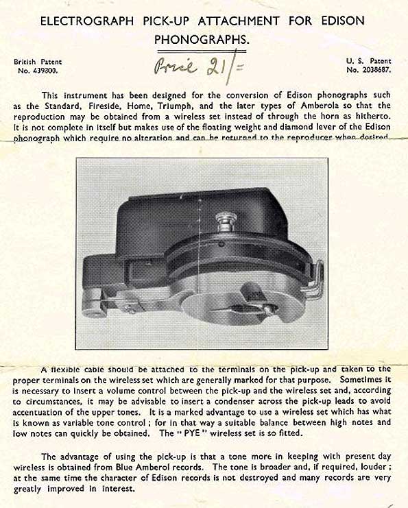
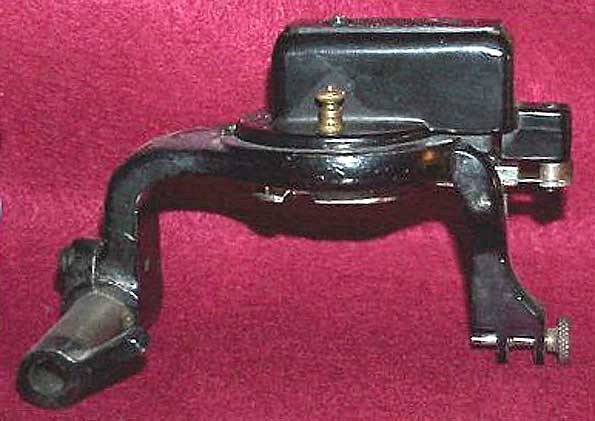
In the 1930's electrical amplification was a well established technology, widely used above all in radio receivers, which often also served as amplifiers for gramophones with electric pick-ups. In the late '20s recording technology had quickly become electrified at the same time as production of phonograph cylinders finally ceased and discs took over the market completely. One of the people working to improve recording and reproducing technology was Adrian Sykes, who filed a number of patent applications in the field. One of his 1934 applications was for an attachment to be used with the floating weight and stylus from an Edison reproducer. This attachment replaced the membrane, soundbox and horn, converting the phonograph to an electric one, to be connected to a radio receiver. The patent mentions Edison phonographs as the machines the attachment was intended for, but does not specify which models. In his collection, Rob Lomas has the device pictured here, made to fit a Diamond B reproducer used with the models Fireside, Standard, Home and Triumph. The construction is an electromagnetic pickup pretty much as they were made at the time, with an iron rod moving inside a coil. The device can be adjusted in two ways, either by sliding the moving magnet up or down by turning a screw on top of the casing (86 in the figure below), or by adjusting the pressure of the plate clamping the rubber sheets around the armature (12 in the figure below). It seems to be a sound construction, and today Rob Lomas finds it sounds "surprisingly good". It appeared on the market at an awkward time, however. It could not have been successful much earlier than the mid '30s, because only by then had amplified radio receivers become commonplace, but production of phonograph cylinders had ceased years before, and thus the Electrograph was at a dead end from day one. It is not known to me how many were produced or in which countries it was sold.
As we can see, the description in the patent is not equal to the actual reproducer in all details, but it gives a good insight into its inner workings. Christer Hamp, 2003
| |||||||||||||||||||||||||||||||||||
|
| ||||||||||||||||||||||||||||||||||
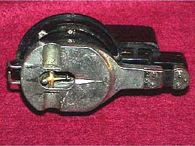
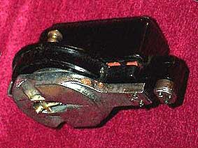
| Two views of the bottom of the reproducer, clearly showing the Sykes reproducer itself in black, contrasting with the shining floating weight from the Edison phonograph | |||||||||||||||||||||||||||||||||||
|
| ||||||||||||||||||||||||||||||||||
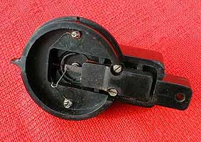
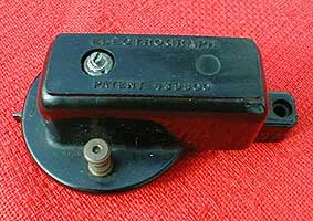
| The Electrograph from below, without the floating weight and stylus assembly. At left the wire that hooks up with the stylus bar, at right the two screws regulating pressure of the plate clamping the rubber sheets around the armature | The Electrograph from above, without the floating weight and stylus assembly. At the top the adjustment screw and below it one of the terminals | ||||||||||||||||||||||||||||||||||
| |||||||||||||||||||||||||||||||||||
| |||||||||||||||||||||||||||||||||||

| If you know anything about the Sykes Electrograph, please write: | Visit Rob Lomas at: | |