
|
Version: April 5, 2008 |
|
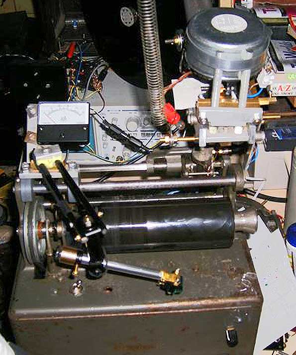
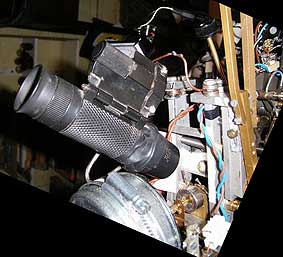
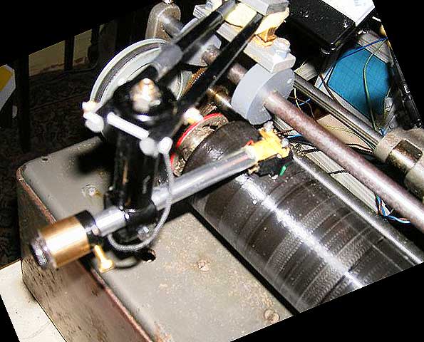
This cylinder recorder and player is every bit as unusual as its name. It is an Ediphone dictaphone that Albert Noble has converted to record narrow band television, the first kind of television, in which the lines in the image are defined by holes in a rotating disk. The method was invented by Paul Nipkow in the 1880's but first put into practice in the 1920's by John Logie Baird. Hence the name of Albert's machine: EDIson and NipKOW make Edikow. So much for etymology, now on to the Edikow itself. In its life as an NBTV recorder it ran at 375 rpm to record the image signal at two frames per revolution. For sound recording the speed has been reduced to a more normal 160 rpm. The groove spacing is .006 inch, as originally on the Ediphone. (Other phonographs use .005 and .010 inch groove spacing) To the left is the short tone arm for playback with its Shure pickup. The arm is suspended from an adjustable arm mounted on a carriage that is advanced by the feedscrew, and thus the tone arm swings very little during playback. To the right is the cutter assembly, raised to its rest position. The round silvery object is the rear of a four inch loudspeaker that is used to drive the stylus. The sapphire stylus - 90° chisel head - is mounted on a parallel motion system which prevents sideways movement during recording. It uses an advance ball, a device that rides on the surface of the cylinder just ahead of the cutting stylus, to ensure a constant average groove depth. This technique is normally used for cutting discs. The advance ball is adjusted with a screw giving .005 inch groove depth adjustment per turn of the screw. An added bonus of the advance ball is that it polishes the wax to a smooth surface before recording. The coil spring seen rising from the cutting assembly is attached to the ceiling, and helps reduce the pressure of the advance ball on the cylinder to be recorded. To make a recording, Albert looks at the stylus tip through the microscope that is mounted in the cutting assembly. By hand, he slowly rotates the cylinder to be cut and adjusts the stylus so that it only just touches the wax surface. Then he lets it cut into the wax to a depth of .0015 inch, giving a .003 inch wide unmodulated groove, with .003 inch land between the grooves. In this way, he calculates that he has a maximum modulation of ± .001 inch. The top frequency response is 9 kHz. On the front of the box can be seen the recording level control - the amplification is mounted inside the case. The µA meter behind the box is the recording level indicator. Christer Hamp, 2008 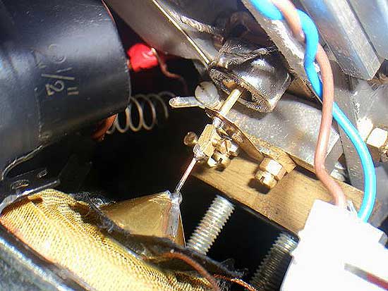
|
|
|
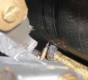
| The recording assembly lowered into place for recording | Closeup of the cutting stylus and advance ball |
|
|

| Write to Albert Noble: | Visit Albert's site Retinascope: | |
