|
Version: October 6, 2013 |
by Keith Harrison, 2013
|
|
|
These carriages were developed to record from phonograph cylinders for the City of London Phonograph and Gramophone Society ‘Reference Series’ books (see www.clpgs.org.uk), and have evolved over time. Two models have been built, designed to replace the original parts on either an Edison Home or Standard phonograph. Model A machines were used for recording, as the speed control is easier than on later versions, but the carriages should suit any Home model or Standard Models A – C. Slight modifications will be necessary to suit later model Standards, and the feedscrew half nut uses a left hand thread on Models D and higher. The designs are aimed to allow a high degree of flexibility in the vertical and lateral movement of the tone arm, to avoid problems caused by shrunken cylinders. They are useable from the front of the player, and do not require permanent modification to the host phonograph. The tone arms allow different cartridge weights to be used. They are fairly easy to make with hand tools (and a fair amount of persistence!) but a model makers’ drill and stand is an advantage in obtaining precision for drilling and tapping small holes – the author used a Proxxon system, which is available fairly cheaply. Materials are easily obtainable from model suppliers, but the service I have received for the following was excellent: Metal bar and sheet was obtained from Chronos on www.chronos.ltd.uk. Pulleys, shafts and bearings came from Technobots on www.technobotsonline.com. All cap screws, grub screws and washers came from Modelfixings on www.modelfixings.co.uk – only 2 mm and 2.5 mm cap screws are used, and drills and taps for these sizes will be needed. Alloy tubing, rubber sheet, sockets, cartridge wire and other minor parts were sourced over the internet or the ‘scrap box’. Some metal bar was supplied in imperial sizes, but metric equivalents have been used in the drawings. I am no draughtsman and these drawings are far from perfect, but if used in conjunction with the photographs give the general idea of the carriages. The drawings were done on graph paper with divisions every 2 mm, and a 1cm line is shown in case printers change the size of the paper. Other than the relationship between the half nut and the carriage pulleys, and the length of the tone arm, dimensions are not critical within a couple of millimetres. The carriage bases differ between the two models, but the arm assembly is the same for both other than the length of the arm. Arm length can be adjusted to cope with different stylus mounts and the balance weight can be varied as well. Shure M44 and Stanton 500 cartridges were used on the prototypes but the head should cope with most models. Styli for both two and four minute records were obtained from Expert Stylus Co. The tone arms can be simply plugged into the ‘phono’ input of a hifi, but this will apply RIAA equalization to the signal resulting in the need to play with the tone controls for cylinder records. I built a small mono preamplifier from a kit (the Velleman K1803 mono pre-amp is cheap and widely available, and can be run on battery power) so that a ‘line’ or ‘aux’ input could be used, which avoids the problem. To remove unwanted noise the cartridge must be wired for vertically cut recordings, as follows: Connect the two ‘live’ cartridge terminals together. Take a mono feed to the preamplifier or computer input from the two earth (ground) pins. On most Shure cartridges the Right Ground pin, normally bottom right when viewed from the rear, should be used as the earth side as some cartridges earth this to the case. Home Carriage
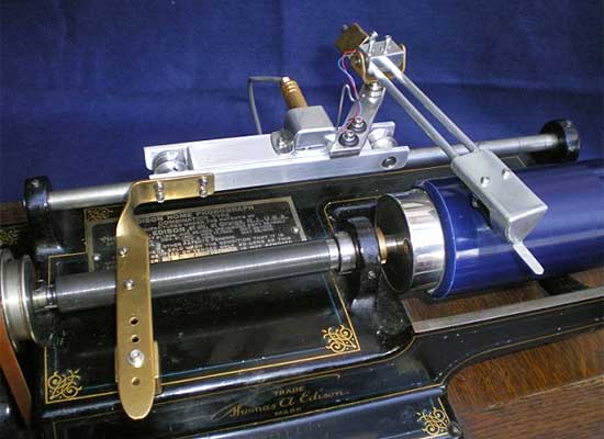
Letters refer to the drawings (link below) The two Side Bars A1 and A2 are epoxied to the Centre Block B. The Counterbalance Bar C is attached to A2 by four 2 mm cap screws, and is bent slightly to the left (as viewed from the front of the phonograph) as necessary to cover the full length of the feedscrew. The Edison half nut, obtained from APSCO (www.antiquephono.com) is aligned to meet the feedscrew after any bending has been done. The level of counterbalance is adjusted by moving weight I. The 3.5 mm jack socket is fitted to the Centre Block, and suitable holes for this must be drilled and tapped. The cover F was made for sockets available on the internet but if others are used it may need modification. The cover is important to reduce any mains hum. The pulleys on which the carriage runs are supplied by Technobots (Part No.4602-013). They run on a short shaft cut from 4 mm steel stock and are held centrally by two alloy washers cut from the end of 4 mm ID tube. Lock the pulley to the shaft using the grub screw supplied. The shaft runs in Flange Bearings (Technobots part 4255-162) fitted in the 8 mm holes drilled in the Side Bars, the bearing flanged facing the pulleys. Ensure the shaft does not foul C. Standard Carriage
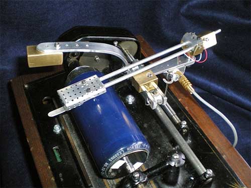
The Standard model uses side pressure from the half nut on the feedscrew, and needs a second weight to keep the carriage on the phonograph back rod smoothly. The assembly is basically the same as the Home type, with Side Bars epoxied onto a Centre Block with pulley assemblies at each end. However the pulleys are reduced in width by cutting off the part holding the grub screw, and tapping for a new 2 mm grub screw into the bottom of the ‘vee’ to clamp the pulley onto the shaft. The pulley runs on the outer part of the vee and doesn’t foul the screw. The additional weight W is screwed onto the right hand end of the carriage to provide more mass and allow the Counterbalance Bar U to keep pressure on the half nut without overbalancing the whole assembly. The Counterbalance Bar is secured with four 2 mm screws onto Side Bar S2. U should be bent slightly to the left to allow the tone arm to ‘see’ the whole length of the cylinder, the amount of movement measured experimentally. The level of counterbalance can be adjusted by moving the weight V. The use of the Carriage Restraints is not vital, but is recommended to avoid accidentally knocking the carriage off the phonograph whilst in use. Ensure that the left pulley shaft is centrally positioned and does not foul either U or X. An APSCO half nut is fitted to plate X, the exact positioning being conducted when the carriage is fitted to the machine. Some relief of the screw slots might be necessary in final adjustment. Plate X is fixed to Side Bar S1 by three 2 mm screws – on some machines the plate may need to be a little wider to ensure that the half nut tracks the whole length of the feed screw. The 3.5 mm jack socket and Cover F are mounted below the Tone Arm Bar Y, drilled and tapped as appropriate. F may require some modification from the drawing as the bar is narrower than the Home carriage, but is essentially the same. Keep the socket as close to the carriage as possible to reduce the counterbalance weight needed. Tone ArmThe tone arm assembly uses a pair of 4 mm OD alloy tubes (Q1 and Q2 – 90 mm long for the Home, 125 mm for the Standard) which are epoxied into the back of the Headshell End Plate L, which itself is epoxied into the folded alloy Headshell K. The precise length of the arm is adjusted by using the two 2.5 mm clamping screws in the Pivot Block M. The Pivot Block is mounted on a 2 mm shaft held between two flange bearings (Technobots 4255-154) and a pair of alloy washers cut from 2 mm ID alloy tube, positioned between the uprights of pivot N. The bearing flanges should face inwards. The shaft is clamped using a 2.5 mm grub screw in the centre hole in M. The balance weight shaft O is epoxied into the blind central 4 mm hole at the rear of M. The size of balance weight P may need experiment as it depends on the weight of the cartridge but 15 mm length suited the prototype Home and 20 mm for the Standard. Exact tracking weights can be adjusted by moving the weight along the shaft and positioned with the clamping screw. The horizontal swivel of the tone arm uses a shaft R held into a 4 mm collet (Technobots) which has been epoxied onto pivot N. This sits on the upper thrust bearing (Technobots 4255-258) and held tightly from below by a flange bearing (Technobots 4255-162) and another collet. This assembly clamps on the Tone Arm Bars made from D/E (Home) and Y/Z (Standard) epoxied together. The Tone Arm Bar is screwed to the carriage by two 2.5 mm screws through a pair of cut down rubber collets, with a 3 mm rubber sheet cushion stuck with contact adhesive below, to provide some protection from mechanical noise. The cartridge is fixed with two 2 mm cap screws, washers and safety nuts. The mounting holes shown worked on the prototypes but if other cartridges are used this may need adjustment. The cartridge is wired in mono as mentioned above, one wire being fed down each tube. These are soldered to the 3.5 mm jack socket, covered by F. A stereo socket is used (wired for mono) as 3.5 mm stereo jack plug and 3.5 mm stereo jack plug/2 phono leads are widely available. Clips to connect the wires to the cartridge were obtained cheaply from the internet, and it is not recommended that any wires are soldered directly to the cartridge pins. The small alloy plate G1 fitted to the rest G will protect the Tone Arm from becoming marked in use, this being simply held with epoxy. The addition of the clip to prevent it from being dislodged from the rest is not vital but is recommended. The split mandrel
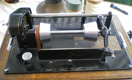
I also have an ACT2 which I had been using to capture precious wax recordings and this was used for recording CDs for the first Reference Series books. One of the problems which quickly emerged was the shrinkage suffered by early indestructibles, this resulting in many cases with the cylinder not fitting the mandrel. Not wanting to ream heavily I used a neighbour’s lathe to make a pair of opposing mandrels to fit a spare Edison Standard A/B shaft, such that the cylinder is gripped at both ends. This was fiddly but worked well for Chicago Lamberts, Edison Bells and Internationals which had suffered serious shrinkage. The distortion stretched the capabilities of the ACT2’s floating arm but with care good results were achieved using a Standard A as speed control is more accessible than later models. Reflective patches were attached to the end of the ‘mini mandrel’ such that a contactless tachometer could be used to set the speed accurately and quickly (£20 from eBay – an absolute must for cylinderophiles). SummaryThese carriages are fairly robust, and have been used to record many cylinders for some time. The author has enjoyed the frustrating task of making them, and the mounting of a spare Standard top on a box containing an electric motor, speed controller and amplifier has allowed electrical replay on demand. This is a source of great entertainment to me, but sadly this is not a sentiment shared by all members of my family! I wish any other builders luck, and if anyone finds improvements to the basic design I would be pleased to hear them. The parts suppliers shown are in the United Kingdom, and it is believed that they will supply internationally but equally these components can be sourced easily in other countries as well. |

| Write to Keith Harrison: | The drawings | Pdf version | |

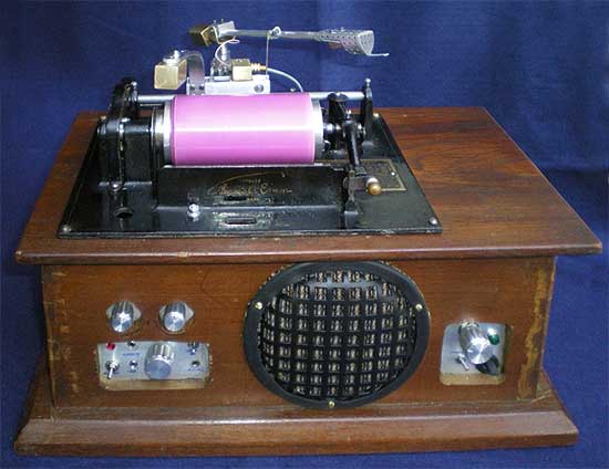 The Electric Standard