|
Version: March 20, 2014 |
By Keith Harrison, 2014
|
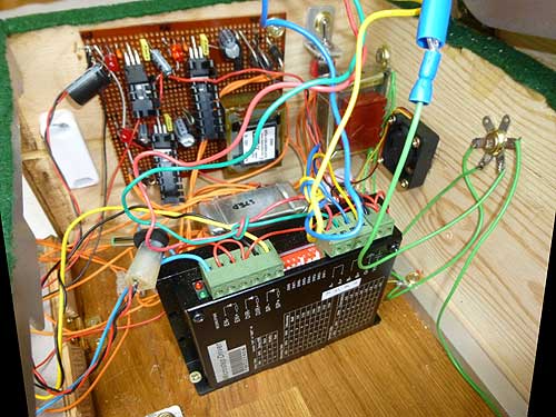
Using my Edison Standard-based machine built in early 2013 gave me more experience in recording cylinders electrically. However it also exposed some shortcomings in the machine, and whetted my appetite for making an improved version. I had an old Edison Home top lying around, which had been found in a market in Mumbai in the early 1970s and which was in very poor condition, so I decided to use this as the basis for the ‘Mk.II’ and not attempt to restore the top to an ‘as new’ state for a project phonograph. One issue which I wanted to address was stability of the mandrel drive. The small DC motor used in my Mk.I machine works well, but is a little noisy and needs constant attention to stay at a precise speed. In 2013 I had seen a demonstration of the magnificent machine constructed by Adrian Tuddenham (described elsewhere on this site) and was impressed with his use of stepper motors to drive the mandrel and feedscrew. Stepper motors might sound counter-intuitive as drives for something which must have smooth running, but Adrian’s clever use of shaped waveforms and soft linkages works very well in practice so I resolved to try the same. I do not have his skill with electronic system design, so began looking on the internet for ‘black boxes’ to do the job such that I could experiment with different arrangements to find the best results. Small but powerful low voltage stepper motors can be obtained cheaply nowadays, as can microstepper drivers. The latter allow the motor to be driven with a number of pulses for each step, which makes the motor run more quietly and ‘softens’ the action of the stepping process. There is also the added advantage of using a higher frequency for the drive, as this both takes the pulse frequency out of the audio range and any ‘stutter’ coming from the stepper motor is absorbed by the mechanical inertia of the drive system. I bought a 12 volt 200 step/revolution motor and a 1.5 amp microstepper driver which allows different settings ranging from 1 to 128 microsteps per step, so to speak. There is a large reduction in torque as the number of microsteps increases, and I wanted to be able to play with the settings to see which gave a smooth drive but still gave the motor enough power to turn the mandrel and drive the tone arm carriage. To feed the stepper driver I needed a frequency generator. I thought of building one from scratch, but simple ‘RC’ generators can be not all that stable so once again I looked on the internet. I found a small computer based signal generator with a phenomenal stability of 1 x 10⁻⁶, a frequency adjustable in 0.01Hz steps, and sine, square, sawtooth and triangle outputs, all of which cost less than a decent lunch, so I obtained one of these.
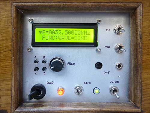
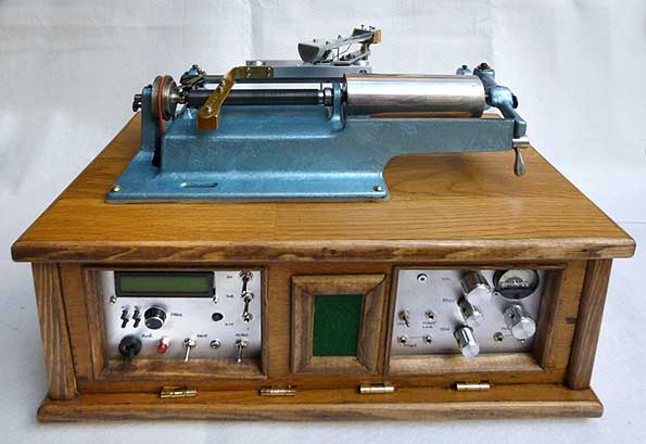
The audio side of things uses easily available two channel preamplifier, active tone control and mono power amp kits. I included an analogue VU meter to help with recording, and this is fed from the preamp channel providing the recording output through a second small amplifier and a home designed diode bridge. The other preamp channel feeds the mono amplifier through the tone control network to a small loudspeaker. There are three home-built stabilized power supplies fed from separate transformers to minimize the chance of stray electrical interference getting into the audio, and the mains supply is fused. The case was made from scratch, which works well but shows my limited skill as a carpenter. The front panel opens downwards to permit maintenance work. The Home top was stripped of the rust and household gloss with which it was covered, and repainted with hammered finish rust proof paint. A good mandrel and feedscrew was obtained, as was a 2/4 minute combination set. The Home carriage described in my article about the Mk.I machine was used to play the cylinders. This uses a Shure M44 cartridge wired for vertical modulation with two and four minute styli supplied by Expert Stylus Co. The motor is mounted on a small light alloy sub chassis, and this is mounted on a larger alloy plate via rubber bushes which in turn is fixed to the Home top by four larger rubber mounts. The rubber blocks are quite soft, and absorb any mechanical vibration coming from the motor. The drive belt is a silicon rubber O ring, which is also fairly soft and absorbs any residual irregularity in the drive train arising from the stepper motor. The pictures show the finished article. The first preamp channel supplies the recording output, and the right hand facia panel has the VU meter, fed from the two parallel line outputs. I used two outputs so that I can have an oscilloscope across the recording feed if required. There are output gain and tone controls for the second preamp channel, which feeds the power amplifier. I had found slight hum pick up when the tone control board was mounted inside the case near the amplifiers so it is now mounted on the back of the facia, to shorten audio wiring runs. This together with earthing all metal parts (including the transformers) and screening the amplifiers cured the problem, and now there is no noticeable hum or other interference in the audio path. There are two headphone sockets and a switch to turn the centrally mounted monitor loudspeaker off if required. There is a line output from the second preamp channel in case there is ever a need for an output with tone control included. The left side facia panel has three power switches, these controlling the drive supplies, the audio and a master. The signal generator screen shows the frequency used, this being set by a rotary knob. There are four small push buttons which control the cursor of the frequency control, the waveform shape, memory stores and other functions. The stepper driver is fed by a 5 volt TTL output, but there is a separate feed connected to a panel mounted output and preset gain control, such that the system can be used as a signal generator for other purposes. The signal generator defaults to 10KHz when switched on, so the ‘Enable’ switch stops the motor drive, but retains the last frequency for the next start which is handy if a number of cylinders are being recorded successively. The ‘Direction’ switch reverses the drive, as I want to experiment with recording cylinders backwards to see if I can coax a better signal from worn wax records.
The input panel at the rear has two 3.5mm jack sockets and a pair of phono sockets, all of these being in parallel. The sockets supply the preamps inside the case but can be used as a patch panel to connect the tone arm directly to other audio devices if needed. The jack sockets are stereo but wired for mono, as are all the sockets on the front facia panels. Also on the rear is a small fan to cool the voltage regulators and the motor, as these get quite warm in use. While the fan is quiet a switch is included so that it can be turned off when recording, such that there can be no noise pick up on the audio feed. I have found the motor runs well at a 16:1 microstep rate, and with the size of the motor pulley and the Home mandrel this requires a 32,500Hz supply for the stepper motor, which is way above the audio range. The sine and square wave outputs both work well, but as the signal generator defaults to sine I normally use this. I cannot detect any step judder by ear, and when playing a 1,000Hz test tone cylinder obtained from Adrian Tuddenham’s Poppy Records there is none visible on an oscilloscope, so the drive experiment has been a success. In use I have found that there is little or no noticeable judder at lower microstep rates but I have set the drive to 16:1 for recording purposes and will conduct further experiments at different rates and waveforms on the ‘Mk.III’ machine now being developed. The phonograph can be used as a domestic player, and I am happily able to irritate my family by playing my music hall cylinders at volume. It can be seen in action in a (very) amateur video (link below) and will be used for recording for the CLPGS Reference Series and for archiving. This will allow me to dismantle the Standard-based Mk.I and remake it as the ‘Mk.III’, which will allow further experimentation and hopefully will include a number of other features including a soft mandrel and a wow reducing system following Adrian’s pioneering work. I am interested in experiences of others in this field, and if I can answer any individual queries please get in touch! (Link below) |

| Write to Keith Harrison: | Watch the video: | |