|
Version: May 9, 2022 |
by Jan Derogee, 2021
|
Why this project? Well, mostly for the fun of it. I decided to build a reproducer because I didn't like the fact that if you wanted to record a cylinder that you needed to hold a microphone in front of the horn of the phonograph. Acoustic coupling just isn't ideal in many ways. So I wondered if that could be improved in a very simple way? Without the use of amplifiers if possible because I'm a bit lazy and adding an amplifier would make it much more difficult for other people to build this project. Now at first the easiest way seems like ripping a pickup element from an old electric record player... but this would be far from ideal. Not only do you destroy a functional record player, you also need to do all sorts of trickery too. For instance the tip of the stylus doesn't really match the tip of the stylus of a cylinder phonograph. which might be an issue. And the fact that the setup requires some form of amplification is a bit silly too even though you can use the guts of the destroyed record player. But, it doesn't have to be that way. Piezo speakers are all around us. You can find them in greetings cards, as parts called piezo buzzers, in alarm clocks and perhaps the most interesting ones are to be found in smoke alarms. Simply because these are the loudest, but mostly because of their size. But despite the size, they are basically are all the same. Although some have an additional segment which is to be used for feedback purposes (to make the perfect oscillator tuned to the resonant frequency of the element) but you do not need to use that connection if you do not want to. So wouldn't it be nice if we could build a pickup element for a phonograph from scratch, using nothing more then a piezo element, resistor, wire, 3.5mm jack, silicone caulk, thick aluminum foil, borosilicate stylus, glue, aluminum tube, cottonwool (or other soft insulation material) and some plastic parts coming out of a 3D printer? Oh... and some screws to keep it all together. Attention: For more information about the stylus, see my other project 3D printed reproducer
Why use a piezo electric speaker for a pickup element? Piezo electric speakers are wonderful things, the piezo electric effect is known for a long time (1880: The Curie brothers demonstrate piezoelectricity). It took some time to evolve from that discovery into a point in time where they are available for next-to-nothing and commonly available and in various convenient sizes. Most likely because you find them in almost every small product that needs to make some form of low fidelity "sound" but allows no room for a decent speaker (and its amplifer). Which allows us to scavenge them from all sorts of products if you do not whish to buy them. The easiest one would be perhaps disposable musical greetings cards. Although keep in mind that not all cards are the same, there are differences. You should go for the card with the loudest and cheapest sounding melody... not the card which has spoken text or allows you to record your own message.
Look mom, no batteries Because piezo electric devices deform when a voltage is applied and generate a voltage when a force is applied. They can generated an electric signal when you scream at them (microphone) or when you allow them to follow the track of a cylinder (pickup element). The voltage generated by the piezo element is proportional to the force applied. And when allowing it to track the groove of a wax cylinder using a stylus, this would result is large mechanical forces onto the element. This mostly because the hills and dales of the groove are very large. In other words, we get plenty of signal from such a huge element when using it to pickup the signal from the cyclinder. In fact... a little bit too much. So we need to reduce it in order to be able to directly connect it to the analog line input of any audio device. A shunt resistor reduces the output level of the piezo element, simply by "consuming" a part of the energy generated by the element. But it does more than that, because a shunt resistor also defines the output impedance of the element into something very high to something defined almost completely by the shunt resistor. And with a shunt resistor of 1 kΩ, we get a device with an output impedance of approx 1 kΩ, which perfectly matches with the line-input requirements of any modern analog input audio device. This also reduces effect of electrical noises like the "traditional" 50/60 Hz interference. This also defines the value of the output to be more consistent as it is less dependent of the input impedance of the connected audio equipment. The shunt resistor also prevents the build up of a DC offset to accidental (when it is not connected but pushed) or residual mechanical stresses. A simple experiment to demonstrate this is gently pressing a piezo speaker and then release the pressure (just a simple short but gentle push), then short the wires, you will hear a short "tick" sound and that's because the shorted wires now allow current from the piezo material to flow and equalize the internal forces between the mechanical deformation of the speaker membrane and the piezo material. Now this effect is a relatively small effect and nobody will ever notice if it is there or not considering that (wax) cylinders aren't really hi-fi equipment after all. But the effect is completely eliminated when using the shunt resistor (which we need anyway for defining the output impedance of the entire device as mentioned earlier). Antoher way of reducing the output volume is by adding more damping material, because if enough of it is stuffed into the case of the device, it will restrict the movement of the element. Now this isn't ideal in many ways, but it gives you some control over the ouput volume in case you really need it. Now you could add a potentiometer to reduce the volume to the point you need it, but that would only make things more complex and honestly, most cylinders are recorded to the same level (which is maximum) and let us not forget that any decent audio recording device will also allow you to scale the input volume.
How I built it There are many ways that this device could have been built. You could for instance use a wooden stick and glue the piezo element directly to that stick. Glue a stylus to the piezo element and you are done. This will work. But, it doesn't like nice and the sound quality slighty suffers. It also is very easy to damage because the fragile piezo element would be fully exposed. And the vibrations of the phonograph itself would easily travel to the element which would allow you to hear the humming of the motor. Altough this isn't such a big deal when you realize that the cylinders make much more nois that you can't really hear that. But it's the thought that counts. Because the concept of using a piezo element as a pickup element is very simple, it works in almost every configuration. But the devil is in the detail. So I experimented a bit with damping materials, like gaskets and cotton wool. And the design I settled for looks much more like an regular reproducer. Considering the similarities it comes as no surprise that this design also produces sound acoustically, although the level of that is very low compared to a real reproducer. The cotton wool is there to dampen these vibrations and make it acoustically a bit more silent. The vibrations of the machine are dampened by the gasket that holds the element in place. Now this isn't perfect, but it is sufficient. I thought of adding a soft rubber hose in the center of the tube that holds everything in place. But considering that the noises of my machine are not noticable in the audio, I did not do that. Simply because it would only make things more complicated. But regarding the gaskets, their true function is (just like in a real reproducer where gaskets are used to hold the membrane) to allow the element to move more freely. But also to dampen possible resonances of the membrane as the soft material adds some "load" to the membrane (piezo element) allowing it to dissipate that mechanical energy. Yes, I could have glued the element directly into the case, that would have worked too. But the addition of the gasket makes it sound just a little bit better. Although I doubt someone will ever notice considering the overal quality of these cylinders, but that a different story. To be completely honest, I really wanted to experiment with making my own gaskets from silicone caulk, so this was a nice excuse to try this out and I'm glad I did it. As it was fun and fun should be an important part in any hobby project, shouldn't it?
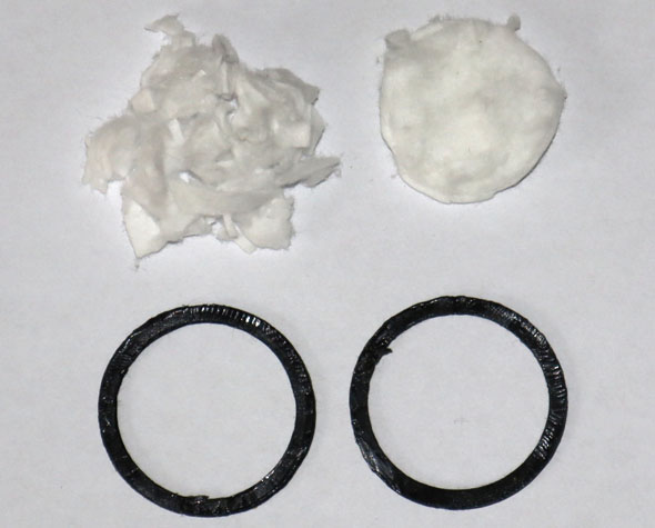
Damping materials Do we need damping materials... well yes we do. And for two reasons. First we need to prevent a hard coupling between the reproducers case and the piezo element. In other words, we do not want to couple the membrane hard to the case and this would lead to undesired resonances and sensitivity to external mechanical vibrations. This is achieved by a pair of soft gaskets, which clamp the piezo element gently and keep it in place. I made these from silicone caulk. Using a 3D printed mold and a glass plate. You should watch the video for more details, it's really easy. Although removing the silicone caulk from the glass plate was a bit more difficult than I expected. I guess I should have coated the glass with some silicone spray perhaps. Anyway, I removed it using a sharp knife which I held firmly against the glass plate while cutting it loose. You can see the cut marks in the photo below, but it hardly removed any significant amount of silicone from the end-product. So no real problem there.
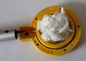
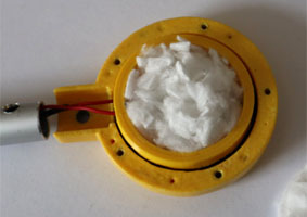
Then we need to prevent the piezo element from resonating and moving too wildly to the applied forces and we also want to prevent the piezo element to function like a conventional membrane, creating audio in the conventional way. Which we can damp using some soft material, some cotton wool will do fine. Anything that's soft and light will do fine. Now you would expect that this is used to fill up the gap, but actually it does a bit more than that. Because you need to fill up the device with a little bit more than that, you'll actually need to "cram in" as much as you can, packing up the material tightly (well tightly is a strongword, as the wool must maintain its fluffiness). At least that is what I did and it gave me good results. The effect of so much cotton wool is simply that it "pushes" against the membrane and prevents it from moving too much. Now regarding cotton wool, as you see in the photo, the material I used is slightly different... but not much. I used makeup cleaning pads, simply because we had nothing else in the house and I assumed my wife would not be missing one or two pads. Because these pads are shaped into discs, I cut them up using scissors into some fine particles so that I regained the fluffiness of cotton wool. But if you have any other kind of fluffy material, I'm sure it will work just as fine. Feel free to experiment.
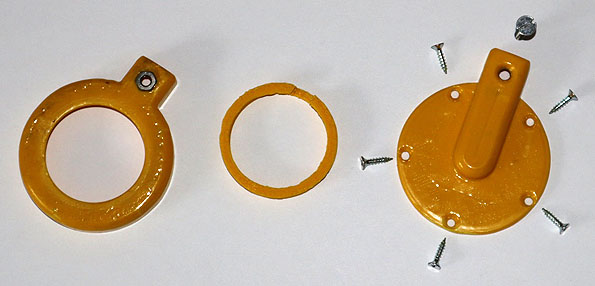
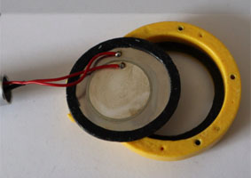
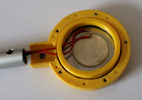
The case In order to use the piezo element, we need some casing for it. A method of holding it in place during use. So I came up with a design that resembles a regular reproducer. Simply because there is pretty much overlap in the goals that need to be achieved. In the image below you see a bottom side, where the sylus protrudes from the device. A clamping ring, to hold the piezo element into place. And a cover to seal it all up. Everything is held together with screws for the simple reason that this allows me to experiment with the configuration of damping materials and such. But when a design like this is completely final, there is no reason why it couldn't be glued completely shut.
How to hook it up
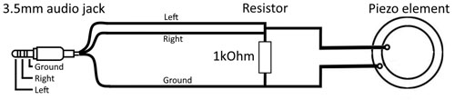
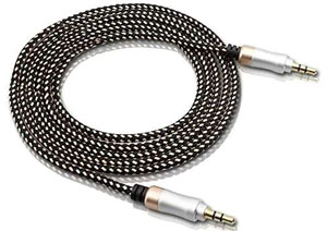
A schematic to show how simple the whole setup is from an electrical perspective. The cable I used was a nice looking 3.5mm audio jack extension cable (a cable with both a male and female connector), from which I cut of the part I needed. But if you want to make two of these devices, then perhaps you should not buy an extension cable but a cable with a 3.5 mm male connector on each side. An image of such a cable is shown below. If you cut up such a cable exactly in the middle you have two usable cables and you do not need to throw anything away. However... the length of the cable might be a bit too short depending on the length of the cable you started with, so keep that in mind! Because nothing is more annoying than a cable that is way too short! Anyway, it all looks a lot prettier when you use a premade cable with the connectors already attached. Also considering the costs of existing cables in the one dollar shop or internet, it would not even be very cost effective to make your own cable.
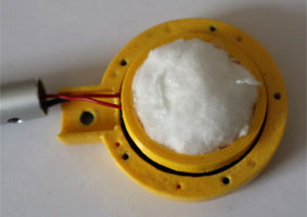
Putting it all together Assembly of all the individual parts is very straight forward, the images below show it step by step. First we need to place the silicone gaskets. One below and one above the piezo element. Then place the clamping ring, this gently pushes against the silicone rings and clamps the piezo element into place. It clamps very gentle, because otherwise we would be compressing the gaskets too much and then they would not be very effective. Then we apply the "cotton wool" and place the cover and the screws to keep it all together.
|
 |
 |
 |
 |
 |
 |
|
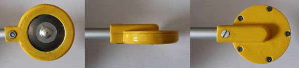
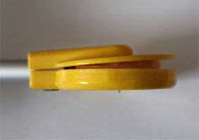
The final result will look like this. Now the critics might say (and they are right to say so) that the M4 screw has a different type of head. The reason for this is simply because my hardware store did not have any other type available <sigh>. Although it looks a bit silly, experiments have shown that the difference can not be heard.
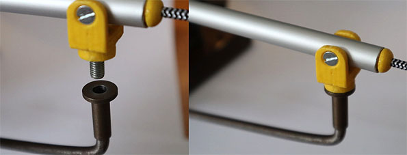
In order to make the whole setup usable it must be connected to the phonograph. And for that we will use the hingingpoint or swivel that is already there for the horn. Since we won't be needing the horn we can use that perfectly. And it seems that the hole is an M6 hole, so if we use an M6 screw we'll be fine. Using an M6 bolt, the hexagonal shape of the head of the bolt will make it fit securely into the 3D printed part.
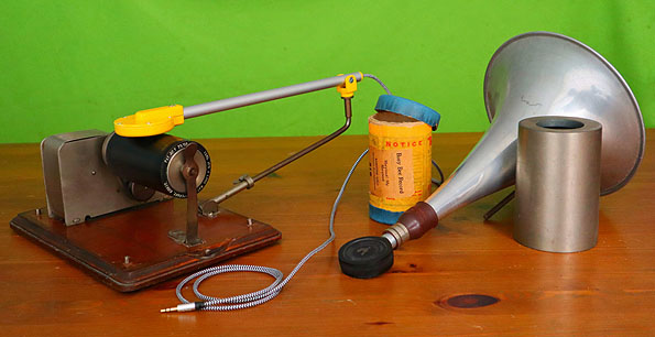
No need to make something special and smooth as it will not be turning very fast. Placing a screw here will not cause wear on the phonograph either because (as mentioned before) it hardly ever moves. During usage (playback of a cylinder) the entire arm rotates only a few degrees, so no need for special bearings because the length of the arm reduces the effect of possible friction (which isn't much to begin with) to something completely negligible. Conclusion This actually works surprisingly well. The signal is strong and clear and the way it is operated is identical to the original configuration of my phonograph. Meaning that the charm of the entire setup (the look-and-feel you might say) is preserved. And more importantly no modifications of any kind had to be made to my precious phonograph, just swap one reproducer for the other and I'm ready to play.
Download section For those of you who would like to hear the recordings I made with this device click here to go to my github page. There you will also find the design files I made in freecad. Although you might need to do some modifications to those files in order to make it fit the piezo element you might be using. I also put the recording on my github page so you'll be able to listen more closely to the results this device produces. The files are stored in the uncompressed format .wav and are therefore much larger than the commonly used MP3. This was done in order to prevent artefacts due to compression, since the cyclinders tend to have a lot of distortion (and therefore harmonics) that the MP3 compression scheme might not be able to handle properly without introducing artefacts. If you which you can always convert these files into MP3 yourselves. There is also a recording from an unknown Dutch singer singing an unknown Dutch song. If you have more information about that song and artist, please let me know so I can adjust the description accordingly. For recording the audio on my computer I used Audacity, a great free program with many features. You can download audacity from: https://www.audacityteam.org/download/
|

| Write to Jan Derogee: | Visit Jan Derogee's site: | |